
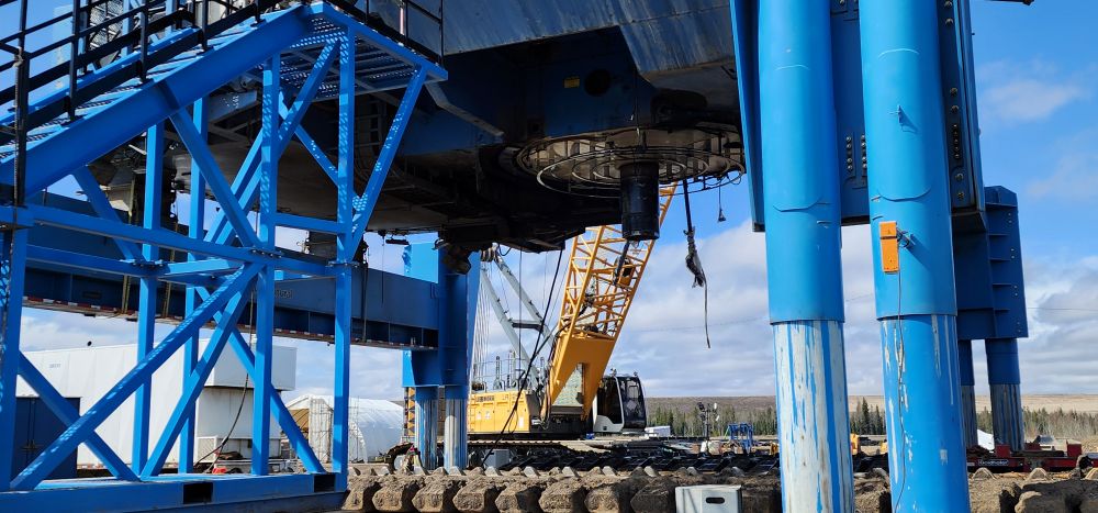
Safety at the Core: Uncompromising Stability in Extreme Conditions
The X‑Lifter is the industry’s most advanced shovel lifter, engineered for safe and efficient shovel lifting operations and compatible with multiple excavator lifting configurations.
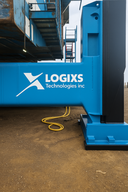
Engineered for unmatched strength and precision, the X‑Lifter is a next‑generation shovel lifter designed for mining operations requiring extreme reliability. With a colossal lifting capacity exceeding 1,300 tons, this advanced shovel lifting equipment redefines maintenance efficiency for the industry’s largest machines.
Designed to lift or split the industry’s largest shovels, its 90‑inch stroke effortlessly separates the upper and lower structures, providing access to pins, bushings, and ample clearance for carbody extraction. This makes the X‑Lifter a highly capable excavator lifting system for heavy mining equipment.
When lifting an entire shovel, the system’s elevation provides clear access to side frames, rollers, and tracks, streamlining maintenance and repairs while improving overall uptime.
The X‑Lifter is built with redundant cylinders in all main jacks, each equipped with hydraulic counterbalance valves to ensure unwavering stability during all shovel lifting or excavator lifting operations.
Its robust safety design allows continued operation even in the rare event of a cylinder failure—maintaining the shovel’s uplifted position without risk of collapse. This ensures maximum reliability in the harshest mining environments, where safe and stable shovel lifter performance is essential.
For hydraulic shovels, the X‑Lifter features a unique three‑foot design that ensures effortless attachment to the machine, enhancing compatibility across shovel and excavator lifter configurations.
This innovation significantly reduces workforce and maintenance costs while improving access to critical components, optimizing efficiency and productivity during heavy‑duty lifting operations.
Numerous other innovations—including a weld‑free saddle that enables lifting an entire shovel with its boom in place—make the X‑Lifter the most comprehensive shovel lifting equipment solution in the industry.
Designed with efficiency in mind, it continues to reduce workforce requirements for shovel maintenance, optimizing operations and minimizing downtime.
The X‑Lifter is fully equipped with a wide range of adapters designed for the industry’s leading shovels and excavators, ensuring seamless compatibility across various models. These include front attachments, weld lugs, under‑boom saddles, shimming blocks, and crane mat cradles, enabling the system to function as both a shovel lifter and a versatile excavator lifting system.
X-Lifter’s Hydraulic Control Unit: At the Heart of the System
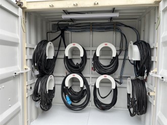
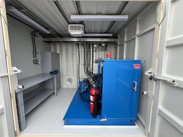
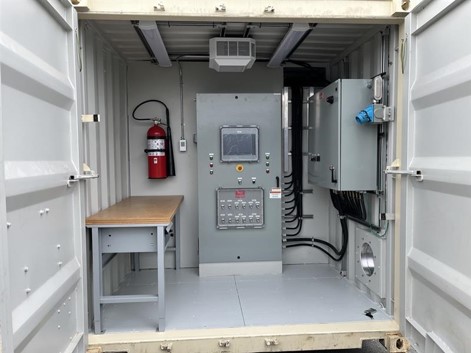
The X‑Lifter hydraulic control unit is engineered for precision and efficiency, featuring a high‑capacity pump, PLC with intuitive display, hydraulic hose reels, and electrical control cables that connect seamlessly to the system’s jacks. The control screen provides real‑time system configurations through a clear visual interface, ensuring operators remain fully aware of operations at all times. Laser sensors on each jack ensure precise level monitoring, while pressure sensors deliver real‑time weight data—critical for safe shovel lifting and excavator lifting operations. The sensor‑based alarm system automatically detects and reacts to out‑of‑norm conditions, ensuring stable and secure operation at all times.
Technical Specifications
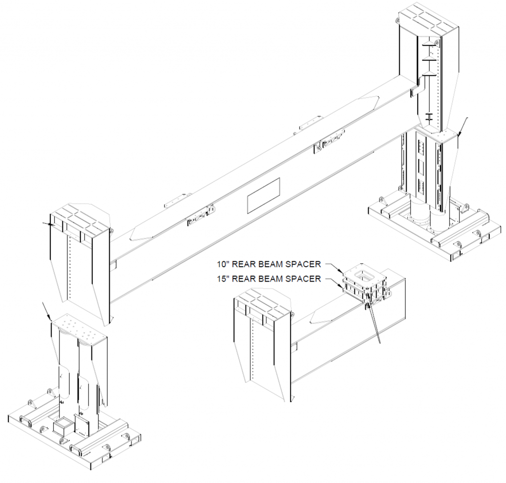
| Rear Beam Assembly | |
|---|---|
| Jacks Configuration | Twin Cylinders |
| Structure Capacity | 750 short tons |
| Jacks Capacity | 680 short tons |
| Stroke | 90″ |
| Horizontal Clearance Between Footings | 44′ 10″ |
| Height adjustments | 96″, 106″, 116″, 126″ |
| Shim Block Heights | 10″, 15″ |
| Footprint (Each Jack) | 12′ x 7’3″ |
| Max Ground Bearing Pressure | 55.3 psi |
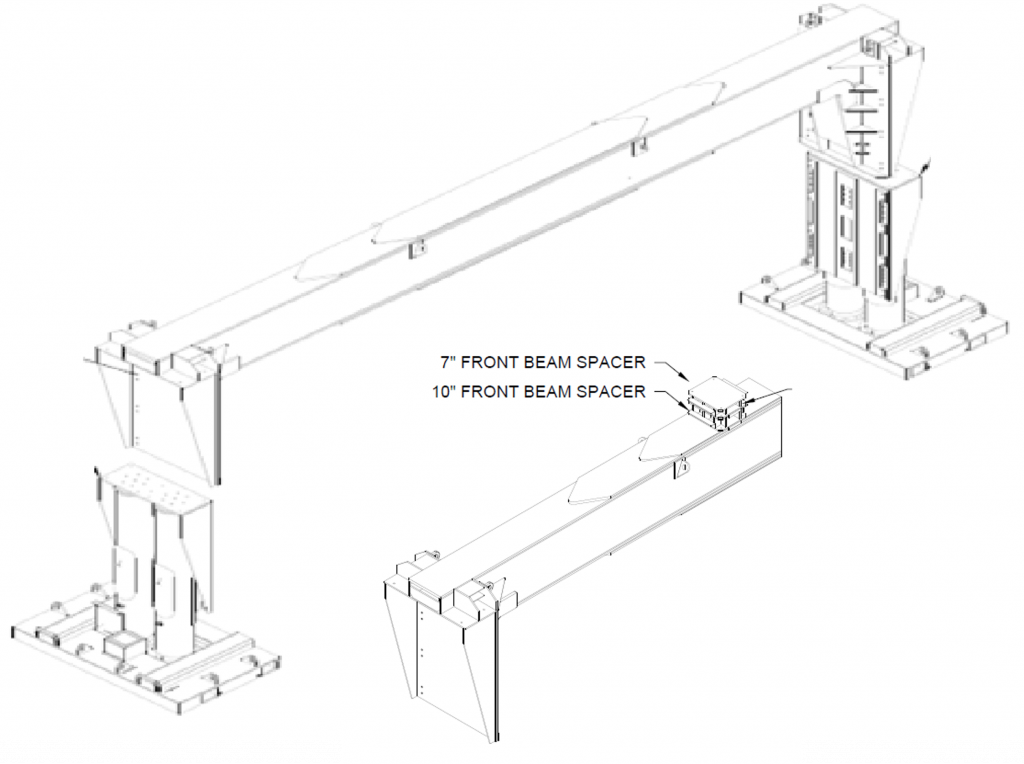
| Front Beam Assembly | |
|---|---|
| Jacks Configuration | Twin Cylinders |
| Structure Capacity | 600 short tons |
| Jacks Capacity | 692 short tons |
| Stroke | 90″ |
| Horizontal Clearance Between Footings | 44′ 11″ |
| Height | 14′ |
| Shim Block Heights | 7″, 10″ |
| Footprint (Each Jack) | 12′ x 7’3″ |
| Ground Bearing Pressure | 55.3 psi |
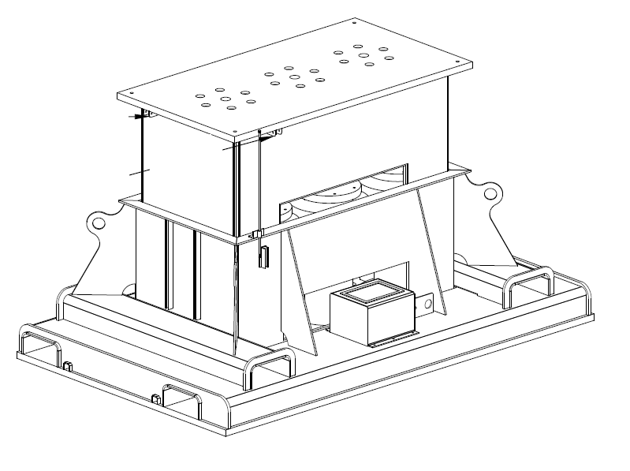
| Carbody Jacks | |
|---|---|
| Jack Configuration | Three Cylinders |
| Jack Capacity | 690 short tons |
| Stroke | 26″ |
| Height | 50″ |
| Footprint (Each Jack) | 12′ x 7’5″ |
| Ground Bearing Pressure | 71 psi |

| Hydraulic Control Unit | |
|---|---|
| Container Dimensions | 10′ x 20′ |
| Tank Volume | 200 US gal |
| Pump | 20 HP, 8 US gal/min., Phase Relay and Front-Rear Starter |
| Twin Hoses & Control Cables (4x) | 75′ |
| Power Cord | 50′ |
| Main Power | 600 V AC, 3-phase, 60 A, 60 Hz |
| Control Panel Supply | 120 V AC, 1-phase, 15 A, 60 Hz |
| Heaters (2x) | 5 kW |
| Control Unit | IFM CR7121S |
| Touch Screen | IFM CR1204 |
| Ports | Ethernet, USB, Canbus |
| Wireless (Optional) | WiFi, BlueTooth |
| Sensors and Controls | |
|---|---|
| Pressure Transmitters (14x) | One per Cylinder |
| Laser Level Sensors (4x) | One per Jack in use |
| Level Switches (2x) | One per Carbody Jack |
| Oil Levels | Level Switch Low (LSL) and Level Switch Low-Low (LSLL) |
| Counter Balance Valves (14x) | One per Cylinder |
| Clogged Swith | On oil Filter |
| Emergency Stop Switches (7x) | One per Jack + Control Room |
| Safety Features | |
|---|---|
| Load Safety Factor | 2x or more |
| Redundant Cylinders | Supports 1 failure per jack |
| Emergency Stop | Per ISO13849-1 Cat 4 |
| Holding Valves Closed on E-Stop | Each Cylinder, Tapped in Body |
| Pump Closed on E-Stop | Inline Starters and Relays |
| PLC Monitoring and Alarms | Imbalances, Pressure, etc. |
| Low Voltage only | All Jacks |
Disclaimer: The specifications and technical information provided are for general reference only
and are subject to change without notice. Logixs Technologies makes no representations or warranties,
express or implied, regarding the accuracy, completeness, or suitability of this information for any
particular purpose. All products must be installed, operated, and maintained in accordance with applicable
codes, standards, and manufacturer instructions. Logixs Technologies shall not be liable for any damages,
losses, or injuries arising from reliance on these specifications or from improper use of the equipment.
Users are solely responsible for verifying the suitability of the system for their intended application.